Implementing Computer Vision for Factory Defect Detection: An Engineering Guide
Learn how to deploy computer vision for factory defect detection. Solve lighting drift, optimize edge AI latency, and handle PLC integration.
If you run a high-speed production line, you know that manual inspection is a bottleneck. Deploying a computer vision system on the factory floor is the standard way to automate quality control. Yet, many manufacturing AI initiatives stall in the lab. They fail because engineers design for static datasets instead of the chaotic physical realities of a factory floor. Building a reliable system for defect detection requires bridging the gap between deep learning models and physical automation hardware.
Why Traditional Machine Vision Fails on the Modern Factory Floor#
Traditional machine vision relies on rigid, pixel-matching rules. You program the system to look for specific pixel values at exact coordinates. This approach works in highly controlled environments. It breaks when product orientation, ambient light, or surface textures vary slightly. If a part is rotated by two degrees or a cloud covers the sun, a rule-based system flags a false positive.
Modern computer vision uses deep learning. Convolutional Neural Networks (CNNs) and Vision Transformers (ViTs) do not look for exact pixel matches. Instead, they generalize features. They identify scratches, dents, or misalignments under real-world conditions, even when the part is dirty or misaligned.
When benchmarking algorithms, researchers use the MVTec AD dataset—which scales to 5,354 high-resolution images across 15 categories—to test unsupervised anomaly detection. But on your physical line, you cannot rely on clean benchmark datasets. You need a system that adapts to real-world chaos.
| Feature | Traditional Machine Vision | Modern Edge AI Computer Vision |
|---|---|---|
| Core Technology | Rule-based, pixel-matching algorithms | Probabilistic deep learning (CNNs, ViTs) |
| Adaptability | Low; requires reprogramming for minor changes | High; generalizes across variations |
| False-Positive Rate | High; sensitive to lighting and placement | Low; filters out environmental noise |
| Hardware Footprint | Standard industrial smart camera | Edge AI gateway (IPC) with GPU/TPU acceleration |
| Deployment Location | Localized on-camera processing | Edge-inference based |
Combating Environmental Drift with Bandpass Filters and IR Lighting#
Do not try to fix bad lighting with software. If your input images are washed out or shadowed, even the most advanced manufacturing AI model will fail. In a real factory, environmental drift is constant. Sunlight shifts through skylights throughout the day. Dust accumulates on lenses. These changes cause typical deep learning false-positive rates of 5% to 15% during initial deployment if you rely on raw ambient light.
Factory vision projects fail when teams optimize for lab accuracy instead of line-speed reliability. Production systems need a physical lighting strategy first. You must solve the physical-to-digital data quality problem at the hardware level before feeding any pixels to a model.
The solution is physical light isolation. Pair a high-frequency strobe light with a physical optical bandpass filter on your camera lens. For example, use an 850nm infrared (IR) LED strobe and a matching 850nm bandpass filter. The filter blocks all visible light—including shifting sunlight and overhead factory lamps—and only allows the 850nm IR light to reach the camera sensor. As a bonus, 850nm IR is invisible to humans. Your high-speed strobe will not distract or fatigue operators working on the line.

The Physical-to-Digital Loop: Edge AI System Architecture#
To build a high-speed defect detection system, you need a deterministic hardware pipeline. Standard webcams or consumer-grade cameras are useless here. You need industrial cameras that use GigE Vision or USB3 Vision standards. These protocols stream raw, uncompressed frames directly to an on-site Industrial PC (IPC) with zero frame drops.
Time is your tightest constraint. Consider a production line moving at 2 meters per second with a 10cm camera field of view. The system has a high-speed inference latency budget of under 50 milliseconds. Within those 50ms, the system must execute the complete physical-to-digital loop:
- Receive the physical trigger from a photoelectric sensor.
- Capture the image via the GigE camera.
- Transfer the raw frame to the IPC.
- Run the edge AI model.
- Output the classification.
- Send the rejection signal to the physical actuator.
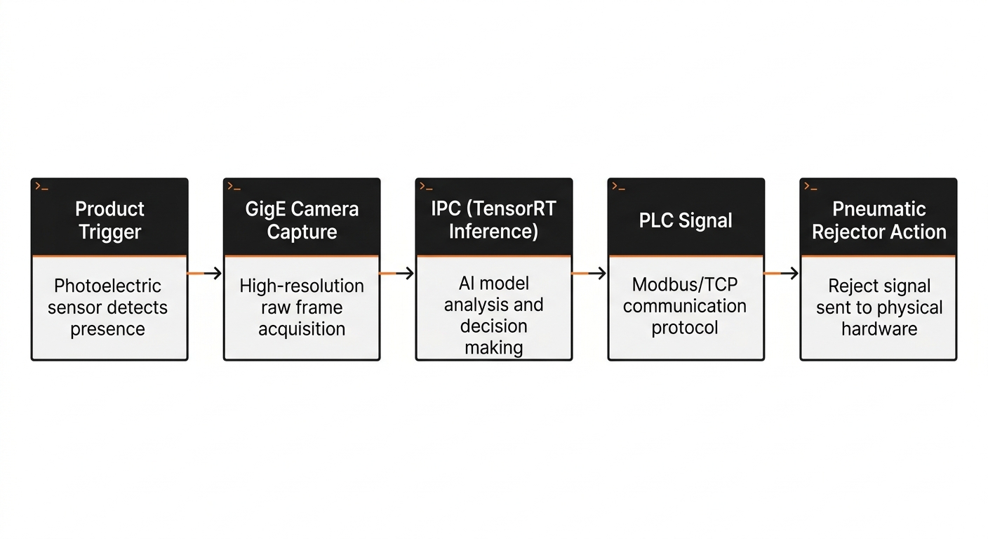
To hit this budget, running raw PyTorch or TensorFlow models is impossible. You must optimize your models. Convert your trained weights into optimized runtimes like NVIDIA TensorRT (for GPU) or Intel OpenVINO (for CPU). This compilation step prunes redundant layers, quantizes FP32 precision to INT8, and fuses operations. It shrinks inference times from 120ms down to 8ms.
The PLC-to-Edge Handshake: Mapping Inference to Physical Rejectors#
Your deep learning model outputs a float value between 0.0 and 1.0 representing a defect probability. A pneumatic rejector piston does not understand float values. It understands a binary 24-volt physical signal. Bridging this gap requires a direct handshake between your IPC and the factory's Programmable Logic Controller (PLC).
Do not use slow, non-deterministic web APIs for this connection. You must use industrial fieldbus protocols over local Ethernet, such as Modbus/TCP, EtherNet/IP, or PROFINET. The IPC acts as a client that writes directly to the PLC's memory registers.
When the edge AI model processes a frame and detects a scratch with a confidence score above your threshold (e.g., 0.85), the inference script immediately writes a 1 to a designated holding register on the PLC. The PLC, operating on a microsecond scan cycle, reads this bit, tracks the product's position along the conveyor using an encoder, and fires the pneumatic rejector at the exact millisecond the defective part passes the rejection station.
Here is how to structure this handshake using Python to write a defect trigger to a PLC register via Modbus/TCP:
from pymodbus.client import ModbusTcpClient
import logging

PLC_IP = "192.168.1.50"
PLC_PORT = 502
DEFECT_REGISTER_ADDRESS = 1001

def trigger_physical_rejector(defect_detected: bool):
    client = ModbusTcpClient(PLC_IP, port=PLC_PORT)
    try:
        if not client.connect():
            logging.error("Failed to connect to PLC")
            return

        # Write 1 (True) to trigger pneumatic rejector, 0 (False) for pass
        value_to_write = 1 if defect_detected else 0
        result = client.write_coils(DEFECT_REGISTER_ADDRESS, [value_to_write])

        if result.isError():
            logging.error(f"Modbus write error: {result}")
        else:
            logging.info(f"Successfully wrote {value_to_write} to PLC register {DEFECT_REGISTER_ADDRESS}")
    finally:
        client.close()
This script removes network jitter by keeping the communication entirely on a local, isolated subnet.
DPDPA 2023 Compliance: Processing Face and Body Redaction at the Edge#
Deploying cameras on factory floors introduces complex regulatory challenges. In India, the Digital Personal Data Protection Act (DPDPA) 2023 dictates how companies handle personal data. If your defect detection cameras capture identifiable images of workers—such as their faces, hands, or distinct physical movements—you are processing personal data.
You cannot bypass this by asking workers to sign broad waivers. Instead, design your system for data minimization. The technical solution is real-time edge-level anonymization.
Before saving any defect logs or sending telemetry to a central database, run a lightweight, secondary object detection model (like a fast MobileNet-SSD) on the IPC. This model specifically detects human faces and bodies. It applies a Gaussian blur to those regions in the raw frame buffer. Only the anonymized frame, containing the isolated product defect, is written to disk or sent to the cloud. The raw, identifiable footage of the human operator never leaves the camera's volatile memory.
Managing the Operational Risks of Edge-Deployed Vision Systems#
Deploying a model is only 20% of the battle. The remaining 80% is keeping it running reliably in a harsh physical environment. Once your system is on the line, three operational risks will threaten its accuracy.
Model Drift#
Your model is trained on a snapshot of your manufacturing process. When your purchasing department sources raw materials from a new vendor, the surface texture might change slightly. Or, a product's packaging design might get a minor update. These subtle changes degrade model accuracy, turning a functional system into a false-alarm generator.
You must build an active learning pipeline. When operators manually override a rejection decision, flag that image, save it locally, and upload it to your training server weekly to retrain and update your model.
Hardware Wear#
Factories are dirty, vibrating environments. Heavy machinery causes continuous micro-vibrations that slowly loosen camera mounts. Over six months, a camera's field of view can shift by several centimeters, throwing off your cropping coordinates. Airborne dust and oil mist will also coat your camera lenses, blurring the image.
To combat this, write automated camera-health monitoring scripts. Have your edge software compare a structural similarity index (SSIM) of the background against a reference image daily. If the SSIM drops below a threshold, trigger a maintenance ticket to clean and realign the camera.
Thermal Throttling#
Industrial PCs running continuous GPU inference generate significant heat. If your assembly line is in a non-climate-controlled warehouse, ambient temperatures can easily exceed 40°C. Standard active-cooled PCs with fans will suck in airborne dust, clog up, and fail. Under high temperatures, the GPU will throttle its clock speed to prevent damage, causing your inference times to spike past your 50ms latency budget.
Always deploy your edge AI models on fanless, passively cooled industrial PCs rated for high thermal performance, and house them in dust-tight NEMA-rated enclosures.
Where to Start: Scoping Your Production Pilot#
Do not try to build a universal defect detection model on day one. A broad scope is the fastest path to a failed project. Instead, select a single high-value defect on a single production line—such as identifying missing caps on a bottling line or surface scratches on an anodized metal part.
Before you write a single line of training code, buy your hardware. Set up your camera, mount your 850nm IR strobe, and install your bandpass filter on the line. Capture 500 images of normal parts and 100 images of defective parts under different shifts. If you can clearly see the defect with your own eyes in those raw images, your deep learning model will easily learn to classify it.
Ensure your engineering team maps out the PLC registers and DPDPA compliance requirements during this initial design phase rather than treating them as post-launch add-ons.
To scale this pilot into a reliable production system, your next step is to run a physical audit of your target assembly line. Measure the belt speed, document the ambient light variations throughout a 24-hour cycle, and identify the exact PLC model running your line. Once you have these physical constraints on paper, you can confidently select your camera sensors and edge hardware.